Introduction
This project enables the use of the OpenBLT bootloader on Bluepill Plus and Blackpill development boards, providing a lightweight and flexible solution for firmware updates on STM32-based systems.
Motivation
This project was developed with the goal of enabling firmware flashing over the CAN protocol for a network of microcontrollers. In future applications—such as an automated aquaponic system for raising fish, crustaceans, and plants—these microcontrollers will manage subsystems like irrigation, lighting, and humidity. Reliable, scalable firmware updates are essential for maintaining such a distributed control system.
STM32F103C8T6 Bluepill plus board
At this stage, the OpenBLT bootloader is fully operational over both RS232 and CAN interfaces on the Bluepill plus board.
The documentation for the device is available in its GitHub repository, and a good summary can also be found on stm32-base.org.
STM32F411CEU6 Blackpill V3.0 board
I’m also evaluating the Blackpill V3.0 board for future use. While it lacks built-in CAN support and is a lower priority for OpenBLT migration, I plan to port the bootloader once the Bluepill-based implementation is complete.
Documentation is available in the board’s GitHub repository. Based on the schematic and hardware details, the STM32F411 MCU appears to be largely compatible with the STM32F403, requiring only minor adaptations for development.
A helpful summary is also provided at stm32-base.org.
OpenBLT Bootloader
OpenBLT is open source and licensed under the GNU General Public License v3 (GPLv3). It was created and is maintained by Feaser. You can visit their official website for more information and documentation.
Test applications
The test applications were obtained from John Blaiklock’s GitHub repository, and the original source code was adapted for this project.
Porting OpenBLT to STM32F103C8Tx
The process to migrate the code of openBLT from STM32F103RB (STM32 Nucleo-64 board) device to STM32F103C8TX (Bluepill plus board) uses the OpenBLT demo project as a base and modifies it to suit the STM32F103C8Tx device.
Download OpenBLT
The complete package of OpenBLT is available in Faser openblt download page
Prepare an environment to work
- Create a working directory for the Bluepill project:
mkdir ~/openBLT_bluepill cd ~/openBLT_bluepill - Copy folders from
openblt_v011901/Target/Demo/ARMCM3_STM32F1_Nucleo_F103RB_GCC/to~/openBLT_bluepill/- Boot/
- Prog/
-
Copy folder
openblt_v011901/Target/Source/ARMCM3_STM32F1/to~/openBLT_bluepill/Source. - Copy the following
.cand.hfiles fromopenblt_v011901/Target/Source/into your~/openBLT_bluepill/Source/directory:openblt_v011901/Target/Source/asserts.c openblt_v011901/Target/Source/asserts.h openblt_v011901/Target/Source/backdoor.c openblt_v011901/Target/Source/backdoor.h openblt_v011901/Target/Source/boot.c openblt_v011901/Target/Source/boot.h openblt_v011901/Target/Source/can.h openblt_v011901/Target/Source/com.c openblt_v011901/Target/Source/com.h openblt_v011901/Target/Source/cop.c openblt_v011901/Target/Source/cop.h openblt_v011901/Target/Source/cpu.h openblt_v011901/Target/Source/file.c openblt_v011901/Target/Source/file.h openblt_v011901/Target/Source/mb.c openblt_v011901/Target/Source/mb.h openblt_v011901/Target/Source/net.c openblt_v011901/Target/Source/net.h openblt_v011901/Target/Source/nvm.h openblt_v011901/Target/Source/plausibility.h openblt_v011901/Target/Source/rs232.h openblt_v011901/Target/Source/timer.h openblt_v011901/Target/Source/usb.h openblt_v011901/Target/Source/xcp.c openblt_v011901/Target/Source/xcp.h - Update device definitions:
Use an existing STM32CubeIDE project targeting the STM32F103C8Tx device. Replace its linker script and startup code with those compatible with OpenBLT.
- Create a new STM32CubeIDE project, Go to File > New > STM32 Project
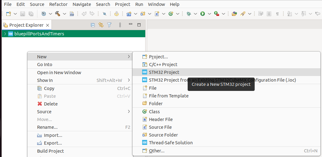
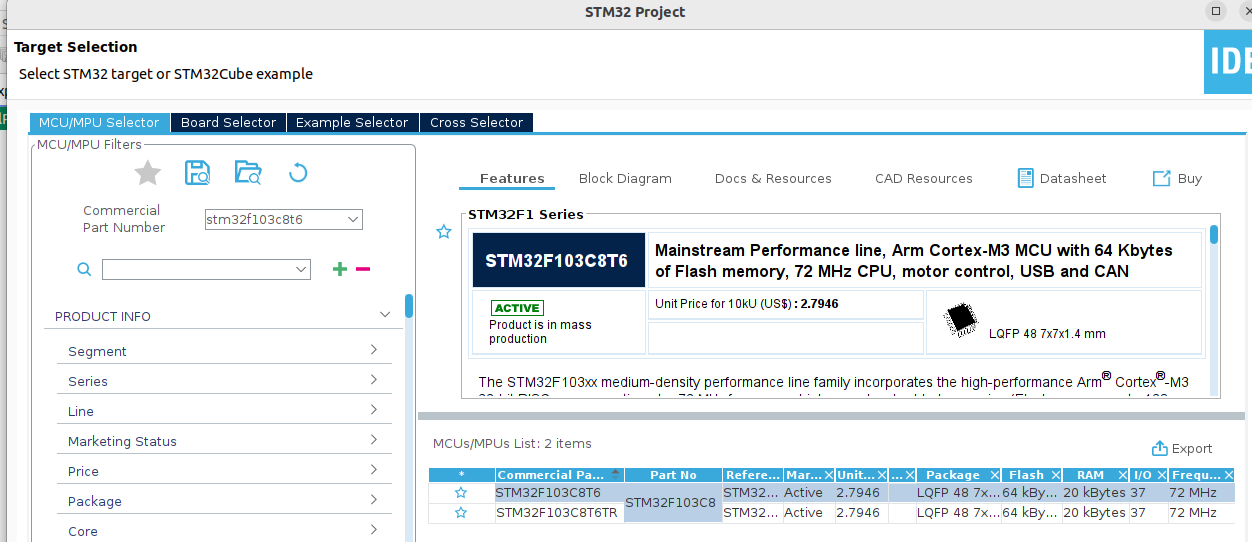
- Select the MCU.
- In the MCU/MPU Selector tab, search for and select STM32F103C8T6.
- Name your project and click Finish.
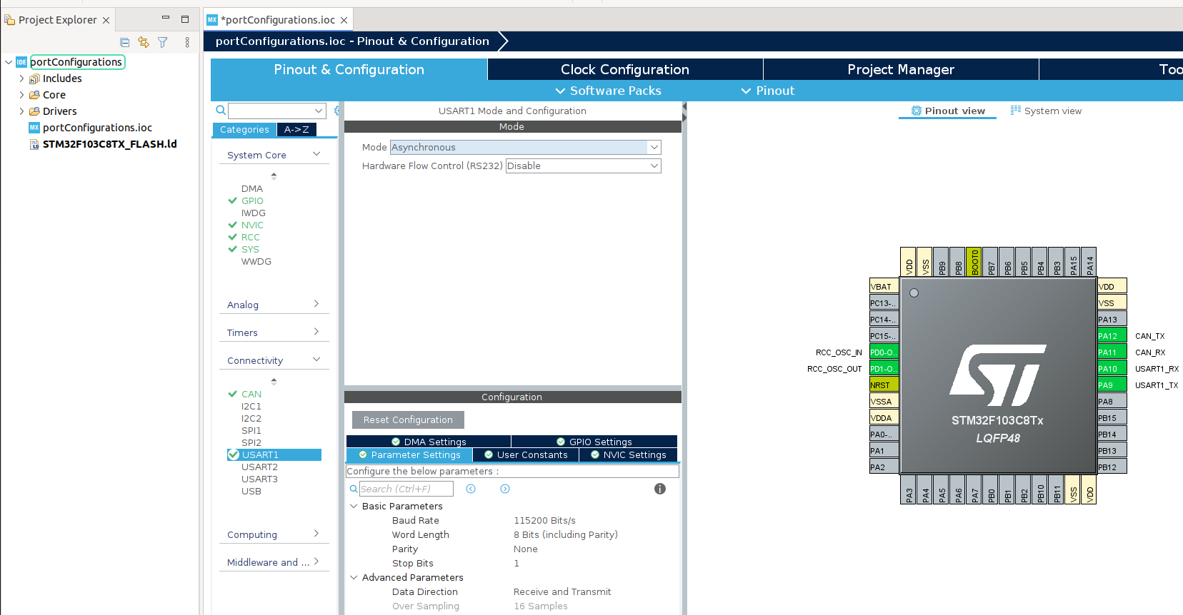
- Configure peripheral settings
- Open the .ioc file of your project.
- Enable the following peripherals:
- CAN Bus
- USART1
- RCC: Set to use HSE (External Clock Source)
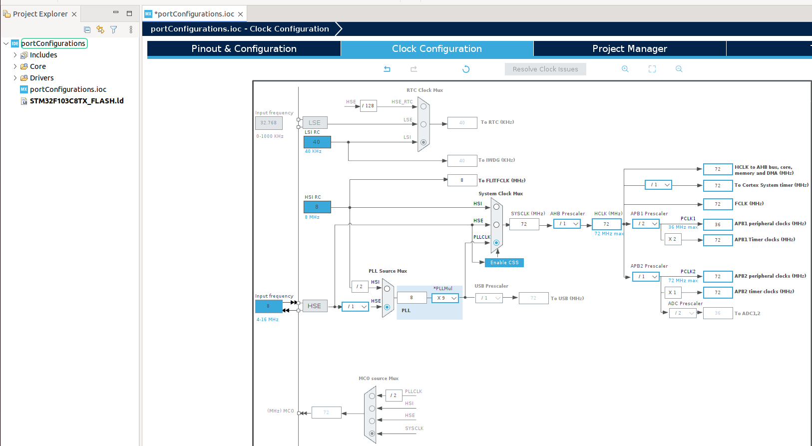
- Configure the system clock.
- Open the Clock Configuration tab.
- Set:
- PLL Source Mux to HSE
- PLLMUL to ×9
- System Clock Mux to PLLCLK
- APB1 Prescaler to /2
- Replace startup files in the OpenBLT project
- Delete the default Nucleo-specific files from OpenBLT:
cd ~/openBLT_bluepill/Boot rm STM32F103RB_FLASH.ld startup_stm32f103xb.s - Copy the files from the STM32CubeIDE-generated project:
  cp ~/STM32CubeIDE/workspace_1.18.1/`YourProjectName`/STM32F103C8TX_FLASH.ld .
  cp ~/STM32CubeIDE/workspace_1.18.1/`YourProjectName`/Core/Startup/startup_stm32f103c8tx.s .
- Delete the default Nucleo-specific files from OpenBLT:
- Change the size of the FLASH memory section in the linker definition.
/* Memories definition */
MEMORY
 {
  RAM    (xrw)    : ORIGIN = 0x20000000,   LENGTH = 20K
-  FLASH    (rx)    : ORIGIN = 0x8000000,   LENGTH = 64K
+  FLASH    (rx)    : ORIGIN = 0x8000000,   LENGTH = 8K
 }
- Create a new STM32CubeIDE project, Go to File > New > STM32 Project
- Compile the project.
- Modify the makefile
Update the Makefile to use your installed ARM toolchain and to reference the correct linker and startup files:#TOOL_PATH=C:/PROGRA~2/GNUTOO~1/82018-~1/bin/ -TOOL_PATH= +TOOL_PATH=~/arm-tools/gcc-arm-none-eabi-10.3-2021.10/bin/ STDFLAGS = -mcpu=cortex-m3 -mthumb -std=gnu11 -fstack-usage -Wall -specs=nano.specs STDFLAGS += -fdata-sections -ffunction-sections -Wall -g -Wno-strict-aliasing -OPTFLAGS = -Os +OPTFLAGS = -Os -flto DEPFLAGS = -MT $@ -MMD -MP -MF $(OBJ_PATH)/$*.d CFLAGS = $(STDFLAGS) $(OPTFLAGS) CFLAGS += -DUSE_FULL_LL_DRIVER -DUSE_HAL_DRIVER -DSTM32F103xB CFLAGS += -D__weak="__attribute__((weak))" -D__packed="__attribute__((__packed__))" CFLAGS += $(INC_PATH) AFLAGS = $(CFLAGS) LFLAGS = $(STDFLAGS) $(OPTFLAGS) -LFLAGS += -T"STM32F103RB_FLASH.ld" -Wl,-Map=$(BIN_PATH)/$(PROJ_NAME).map +LFLAGS += -T"STM32F103C8TX_FLASH.ld" -Wl,-Map=$(BIN_PATH)/$(PROJ_NAME).map LFLAGS += -Wl,--gc-sections $(LIB_PATH) OFLAGS = -O srec ODFLAGS = -x SZFLAGS = -B -d RMFLAGS = -f ... #| Make ALL | #|--------------------------------------------------------------------------------------| +.PHONY: prepare_dirs +prepare_dirs: +mkdir -p $(OBJ_PATH) +mkdir -p $(BIN_PATH) .PHONY: all -all: $(BIN_PATH)/$(PROJ_NAME).srec +all: prepare_dirs $(BIN_PATH)/$(PROJ_NAME).srec $(BIN_PATH)/$(PROJ_NAME).srec : $(BIN_PATH)/$(PROJ_NAME).elf ... @echo +++ Linking [$(notdir $@)] @$(LN) $(LFLAGS) -o $@ $(patsubst %.o,$(OBJ_PATH)/%.o,$(^F)) $(LIBS) +.PHONY: $(BIN_PATH)/$(PROJ_NAME).bin +$(BIN_PATH)/$(PROJ_NAME).bin: + @$(OC) -O binary $(BIN_PATH)/$(PROJ_NAME).elf $@ + #|--------------------------------------------------------------------------------------| #| Compile and assemble | - Test the Compilation
Navigate to the project folder and compile:
cd ~/openBLT_bluepill/Boot/
make clean all
If everything is set up correctly, the build process should complete without errors and generate the firmware binaries.
- Modify the makefile
- You are now ready to port the source.
Configure and deploy the OpenBLT bootloader on the Bluepill board.
To enable communication over UART and CAN interfaces with OpenBLT on the Bluepill board (STM32F103C8T6), you will need to modify several source files in the Boot/ directory. These changes configure how the bootloader interacts with the microcontroller’s hardware.
Hardware considerations
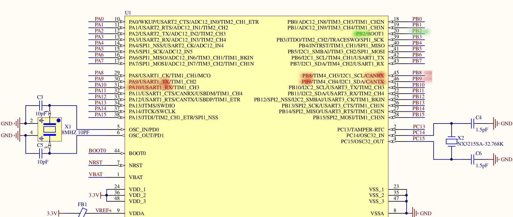
The original NUCLEO-STM32F103RB board uses USART2 for serial communication, with USART2 RX on Port A3 and USART2 TX on Port A2. It also uses CAN1 for CAN communication, typically remapped to CAN_RX on Port B8 and CAN_TX on Port B9 via the alternate function remap feature. Additionally, the user LED on the NUCLEO board is connected to Port A5.
UART
For this project, UART communication will use USART1, which is mapped to:
- USART1 TX: Port A9
- USART1 RX: Port A10
These pins are standard on the Bluepill board for USART1 and are supported by the hardware.
CAN
For CAN communication on the Bluepill Plus board, CAN1 is used. The pin mapping remains the same as on the NUCLEO board due to the use of alternate function remapping:
- CAN1_RX: Port B8
- CAN1_TX: Port B9
GPIOs
-
The backdoor entry mechanism is not considered in this project, as future applications are unlikely to require it. For this reason, GPIO Port C13, which is typically used for the backdoor entry in OpenBLT, will be disabled in this configuration.
-
The user LED on the Bluepill Plus board is connected to Port B2. This differs from the original Nucleo board (which uses Port A5), so the LED configuration in the OpenBLT project must be updated accordingly to reflect this hardware change.
Hardware connections:
The picture presents the system.
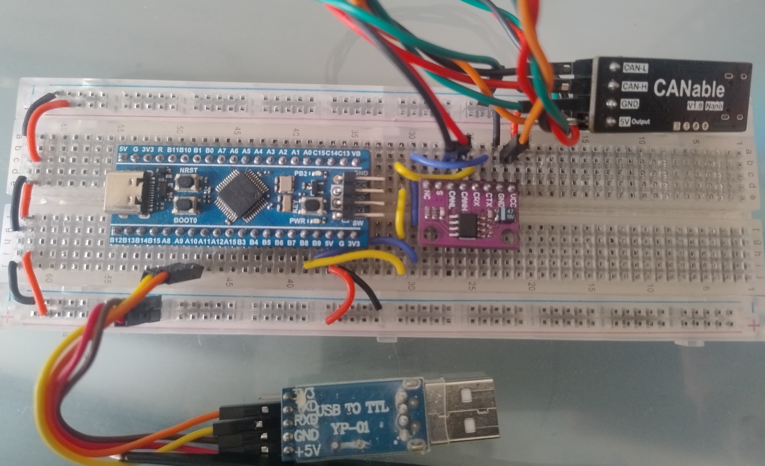
The system is composed of the following components:
- Bluepill Plus Board
A modified version of the classic STM32F103C8T6 Bluepill board, equipped with more stable power delivery and cleaner GPIO layout. -
USB to TTL Adapter
Based on the PL2303 USB-to-serial chip, this adapter provides a UART interface between the PC and the Bluepill Plus board, used for firmware updates via UART.
Connect the GPIO pins as specified in the table below:Resource GPIO Board Connector Device USART1_TX PA9 A9 USB to TTL - Rx USART1_RX PA10 A10 USB to TTL - Tx 5V – 5V USB to TTL - 5V GND – GND USB to TTL - GND - CTJA1051 CAN Transceiver
A high-speed CAN transceiver that interfaces the STM32’s CAN peripheral with the physical CAN bus. It handles signal level conversion and bus protection. -
CANable v1.0 Nano
A USB-to-CAN adapter that connects the system to a PC over USB. It enables firmware uploads and communication over the CAN bus using protocols like slcan or candlelight firmware.
The CANable device should be connected directly to the TJA1051 transceiver, which serves as the interface between the microcontroller and the CAN bus. This setup ensures proper voltage level translation and signal integrity for reliable CAN communication.CTJA1051 CANable V1.0 Nano CAN-L CAN-L CAN-H CAN-H 5V 5V GND GND
The TJA1051 transceiver should be connected to the microcontroller’s GPIO pins as specified in the table below:
| Resource | GPIO | Board Connector | Device |
|---|---|---|---|
| CAN1_RX | PB8 | B8 | CTJA1051 - CRx |
| CAN1_TX | PB9 | B9 | CTJA1051 - CTx |
| 5V | – | 5V | CTJA1051 - 5V |
| GND | – | GND | CTJA1051 - GND |
Software Changes
blt_conf.h — Bootloader Configuration Header
This file contains compile-time options that define how OpenBLT behaves. You must enable the appropriate communication interfaces (UART and CAN). To activate UART and CAN you should check that ports are enable in the correct channel to the case to the Bluepill:
- UART: Only change the chanel to 0 because the used port will be UART1.
/** \brief Enable/disable UART transport layer. */ #define BOOT_COM_RS232_ENABLE (1) /** \brief Configure the desired communication speed. */ #define BOOT_COM_RS232_BAUDRATE (57600) /** \brief Configure number of bytes in the target->host data packet. */ #define BOOT_COM_RS232_TX_MAX_DATA (129) /** \brief Configure number of bytes in the host->target data packet. */ #define BOOT_COM_RS232_RX_MAX_DATA (129) /** \brief Select the desired UART peripheral as a zero based index. */ -#define BOOT_COM_RS232_CHANNEL_INDEX (1) +#define BOOT_COM_RS232_CHANNEL_INDEX (0) - CAN: To this example CAN do not need changes.
#define BOOT_COM_CAN_ENABLE             (1)
/** \brief Configure the desired CAN baudrate. */
#define BOOT_COM_CAN_BAUDRATE           (500000)
/** \brief Configure CAN message ID target->host. */
#define BOOT_COM_CAN_TX_MSG_ID          (0x7E1 /*| 0x80000000*/)
/** \brief Configure number of bytes in the target->host CAN message. */
#define BOOT_COM_CAN_TX_MAX_DATA        (8)
/** \brief Configure CAN message ID host->target. */
#define BOOT_COM_CAN_RX_MSG_ID          (0x667 /*| 0x80000000*/)
/** \brief Configure number of bytes in the host->target CAN message. */
#define BOOT_COM_CAN_RX_MAX_DATA        (8)
/** \brief Select the desired CAN peripheral as a zero based index. */
#define BOOT_COM_CAN_CHANNEL_INDEX      (0)
main.c
This file must be updated to configure the system clock, GPIOs, and peripherals required by OpenBLT. These include:
- System clock initialization (matching the PLL settings from STM32CubeIDE).
- GPIO configuration for the LED (Port B2).
- Initialization of USART1 for UART communication (TX: PA9, RX: PA10).
- Initialization of CAN1 (RX: PB8, TX: PB9 with remapping if necessary).
-
Disabling or removing the backdoor entry GPIO setup (e.g., PC13).
Note: The backdoor feature in this project’s architecture requires further consideration for future use. For now, simply disabling the corresponding GPIO pin configuration is sufficient. This approach avoids unnecessary complexity while maintaining compatibility with OpenBLT. - GPIO Deinitialization.
static void SystemClock_Config(void)
{
-  /* Set flash latency. */
-  LL_FLASH_SetLatency(LL_FLASH_LATENCY_2);
-  if (LL_FLASH_GetLatency() != LL_FLASH_LATENCY_2)
-  {
-    /* Error setting flash latency. */
-    ASSERT_RT(BLT_FALSE);
-  }
-
-  /* Enable the HSE clock. */
-  LL_RCC_HSE_EnableBypass();
-  LL_RCC_HSE_Enable();
-  /* Wait till HSE is ready. */
-  while (LL_RCC_HSE_IsReady() != 1)
-  {
-    ;
-  }
-
-  /* Configure and enable the PLL. */
-  LL_RCC_PLL_ConfigDomain_SYS(LL_RCC_PLLSOURCE_HSE_DIV_1, LL_RCC_PLL_MUL_9);
-  LL_RCC_PLL_Enable();
-
-  /* Wait till PLL is ready. */
-  while (LL_RCC_PLL_IsReady() != 1)
-  {
-    ;
-  }
-  LL_RCC_SetAHBPrescaler(LL_RCC_SYSCLK_DIV_1);
-  LL_RCC_SetAPB1Prescaler(LL_RCC_APB1_DIV_2);
-  LL_RCC_SetAPB2Prescaler(LL_RCC_APB2_DIV_1);
-  LL_RCC_SetSysClkSource(LL_RCC_SYS_CLKSOURCE_PLL);
-  /* Wait till System clock is ready. */

-  while (LL_RCC_GetSysClkSource() != LL_RCC_SYS_CLKSOURCE_STATUS_PLL)
- {
-    ;
-  }
-  /* Update the system clock speed setting. */
-  LL_SetSystemCoreClock(BOOT_CPU_SYSTEM_SPEED_KHZ * 1000u);
+   RCC_OscInitTypeDef RCC_OscInitStruct = {0};
+   RCC_ClkInitTypeDef RCC_ClkInitStruct = {0};
+
+  /** Initializes the CPU, AHB and APB busses clocks
+  */
+  RCC_OscInitStruct.OscillatorType = RCC_OSCILLATORTYPE_HSE;
+  RCC_OscInitStruct.HSEState = RCC_HSE_ON;
+  RCC_OscInitStruct.HSEPredivValue = RCC_HSE_PREDIV_DIV1;
+  RCC_OscInitStruct.HSIState = RCC_HSI_ON;
+  RCC_OscInitStruct.PLL.PLLState = RCC_PLL_ON;
+  RCC_OscInitStruct.PLL.PLLSource = RCC_PLLSOURCE_HSE;
+  RCC_OscInitStruct.PLL.PLLMUL = RCC_PLL_MUL9;
+  if (HAL_RCC_OscConfig(&RCC_OscInitStruct) != HAL_OK)
+  {
+    ;
+  }
+  /** Initializes the CPU, AHB and APB busses clocks
+  */
+  RCC_ClkInitStruct.ClockType = RCC_CLOCKTYPE_HCLK|RCC_CLOCKTYPE_SYSCLK
+                              |RCC_CLOCKTYPE_PCLK1|RCC_CLOCKTYPE_PCLK2;
+  RCC_ClkInitStruct.SYSCLKSource = RCC_SYSCLKSOURCE_PLLCLK;
+  RCC_ClkInitStruct.AHBCLKDivider = RCC_SYSCLK_DIV1;
+  RCC_ClkInitStruct.APB1CLKDivider = RCC_HCLK_DIV2;
+  RCC_ClkInitStruct.APB2CLKDivider = RCC_HCLK_DIV1;
+
+  if (HAL_RCC_ClockConfig(&RCC_ClkInitStruct, FLASH_LATENCY_2) != HAL_OK)
+  {
+    ;
+  }
} /*** end of SystemClock_Config ***/
...
#if (BOOT_COM_RS232_ENABLE > 0)
   /* UART clock enable. */
-  LL_APB1_GRP1_EnableClock(LL_APB1_GRP1_PERIPH_USART2);
+  LL_APB2_GRP1_EnableClock(LL_APB2_GRP1_PERIPH_USART1);
#endif
#if (BOOT_COM_CAN_ENABLE > 0)
/* CAN clock enable. */
   LL_APB1_GRP1_EnableClock(LL_APB1_GRP1_PERIPH_CAN1);
#endif
/* Configure GPIO pin for the LED. */
-  GPIO_InitStruct.Pin = LL_GPIO_PIN_5;
+  GPIO_InitStruct.Pin = LL_GPIO_PIN_2;   //LED connected to PB2
   GPIO_InitStruct.Mode = LL_GPIO_MODE_OUTPUT;
   GPIO_InitStruct.Speed = LL_GPIO_SPEED_FREQ_LOW;
   GPIO_InitStruct.OutputType = LL_GPIO_OUTPUT_PUSHPULL;
-  LL_GPIO_Init(GPIOA, &GPIO_InitStruct);
-  LL_GPIO_ResetOutputPin(GPIOA, LL_GPIO_PIN_5);
+  LL_GPIO_Init(GPIOB, &GPIO_InitStruct);
+  LL_GPIO_ResetOutputPin(GPIOB, LL_GPIO_PIN_2);
   /* Configure GPIO pin for (optional) backdoor entry input. */
#if (BOOT_BACKDOOR_HOOKS_ENABLE > 0)
    GPIO_InitStruct.Pin = LL_GPIO_PIN_13;
    GPIO_InitStruct.Mode = LL_GPIO_MODE_FLOATING;
    LL_GPIO_Init(GPIOC, &GPIO_InitStruct);
+#endif
#if (BOOT_COM_RS232_ENABLE > 0)
   /* UART TX and RX GPIO pin configuration. */
- GPIO_InitStruct.Pin = LL_GPIO_PIN_2;
+ GPIO_InitStruct.Pin = LL_GPIO_PIN_9;   //TX: Serial1 PA9
  GPIO_InitStruct.Mode = LL_GPIO_MODE_ALTERNATE;
  GPIO_InitStruct.Speed = LL_GPIO_SPEED_FREQ_HIGH;
  GPIO_InitStruct.OutputType = LL_GPIO_OUTPUT_PUSHPULL;
  LL_GPIO_Init(GPIOA, &GPIO_InitStruct);
- GPIO_InitStruct.Pin = LL_GPIO_PIN_3;
+ GPIO_InitStruct.Pin = LL_GPIO_PIN_10; //RX: Serial1 PA10-
  GPIO_InitStruct.Mode = LL_GPIO_MODE_FLOATING;
  LL_GPIO_Init(GPIOA, &GPIO_InitStruct);
#endif
...
if (BOOT_COM_CAN_ENABLE > 0)
  /* CAN clock disable. */
  LL_APB1_GRP1_DisableClock(LL_APB1_GRP1_PERIPH_CAN1);
#endif
#if (BOOT_COM_RS232_ENABLE > 0)
   /* UART clock disable. */
-  LL_APB1_GRP1_DisableClock(LL_APB1_GRP1_PERIPH_USART2);
+  LL_APB2_GRP1_DisableClock(LL_APB2_GRP1_PERIPH_USART1);
#endif
led.c
This file manages the user LED functionality to indicate the bootloader’s activity. Locate the GPIO configuration code and change it to reflect the new pin:
void LedBlinkTask(void)
{
  static blt_bool ledOn = BLT_FALSE;
  static blt_int32u nextBlinkEvent = 0;

  /* check for blink event */
  if (TimerGet() >= nextBlinkEvent)
  {
    /* toggle the LED state */
    if (ledOn == BLT_FALSE)
    {
      ledOn = BLT_TRUE;
-      LL_GPIO_SetOutputPin(GPIOA, LL_GPIO_PIN_5);
+      LL_GPIO_SetOutputPin(GPIOB, LL_GPIO_PIN_2);
    }
    else
    {
      ledOn = BLT_FALSE;
-      LL_GPIO_ResetOutputPin(GPIOA, LL_GPIO_PIN_5);
+      LL_GPIO_ResetOutputPin(GPIOB, LL_GPIO_PIN_2);
    }
    /* schedule the next blink event */
    nextBlinkEvent = TimerGet() + ledBlinkIntervalMs;
  }
} /*** end of LedBlinkTask ***/
...
void LedBlinkExit(void)
{
  /* turn the LED off */
-  LL_GPIO_ResetOutputPin(GPIOA, LL_GPIO_PIN_5);
+  LL_GPIO_ResetOutputPin(GPIOB, LL_GPIO_PIN_2);
} /*** end of LedBlinkExit ***/
Preparing the Demo Application for the Bluepill Plus
The Prog/ folder contains a demo application featuring a blinking LED. This application serves two main purposes:
- To verify that firmware flashing via OpenBLT is functioning correctly.
- To provide a working example that uses the correct memory layout for compatibility with the bootloader.
Just like the bootloader project in the Boot/ folder, several files in the Prog/ application must be modified to match the Bluepill Plus hardware and the memory configuration used by OpenBLT.
Files to Modify
Makefile
Update the toolchain path and optimization flags in the Makefile to match those used in the bootloader. This ensures compatibility and correct use of the installed ARM toolchain.
-TOOL_PATH =
+TOOL_PATH = ~/arm-tools/gcc-arm-none-eabi-10.3-2021.10/bin/

-OPTFLAGS = -Os
+OPTFLAGS = -Os -flto
Also, update the linker script to use one aligned with the bootloader’s memory reservation (e.g., skipping the first 16 KB of flash for OpenBLT):
-LFLAGS     += -T"STM32F103RB_FLASH.ld" -Wl,-Map=$(BIN_PATH)/$(PROJ_NAME).map
+LFLAGS     += -T"STM32F103C8TX_FLASH.ld" -Wl,-Map=$(BIN_PATH)/$(PROJ_NAME).map
Linker File
You must use a custom linker script for the application, to ensure that the firmware starts after the bootloader. For example, if the bootloader occupies the first 0x2000 (8KB) of flash:
/* Memories definition */
MEMORY
{
  RAM    (xrw)    : ORIGIN = 0x20000000,   LENGTH = 20K
-  FLASH    (rx)    : ORIGIN = 0x8000000,   LENGTH = 64K
+  FLASH    (rx)    : ORIGIN = 0x8002000,   LENGTH = 64K-8K
}
Startup file
For the application project in Prog/, you need to reserve space for the checksum in the startup file. OpenBLT uses this 32-bit checksum to verify the integrity of the application firmware during the boot process.
.word RTC_Alarm_IRQHandler
.word USBWakeUp_IRQHandler
.word 0
.word 0
.word 0
.word 0
.word 0
.word 0
.word 0
.word BootRAM          /* @0x108. This is for boot in RAM mode for
                            STM32F10x Medium Density devices. */
+ .word     0x55AA11EE   /* Reserved for OpenBLT checksum*/

/******************************************************************************
main.c
Modify the GPIO and peripheral configuration in main.c to match the Bluepill Plus hardware layout.
/* initializes the CPU, AHB and APB busses clocks */
RCC_OscInitStruct.OscillatorType = RCC_OSCILLATORTYPE_HSE;
RCC_OscInitStruct.HSEState = RCC_HSE_ON;
RCC_OscInitStruct.HSEPredivValue = RCC_HSE_PREDIV_DIV1;
RCC_OscInitStruct.HSIState = RCC_HSI_ON;
...
#if (BOOT_COM_RS232_ENABLE > 0)
/* Peripheral clock enable. */
-__HAL_RCC_USART2_CLK_ENABLE();
+__HAL_RCC_USART1_CLK_ENABLE();
#endif /* BOOT_COM_RS232_ENABLE > 0 */
...
/* Configure the LED GPIO pin. */
-GPIO_InitStruct.Pin = GPIO_PIN_5;
+GPIO_InitStruct.Pin = GPIO_PIN_2;
GPIO_InitStruct.Mode = GPIO_MODE_OUTPUT_PP;
GPIO_InitStruct.Pull = GPIO_NOPULL;
GPIO_InitStruct.Speed = GPIO_SPEED_FREQ_LOW;
-HAL_GPIO_Init(GPIOA, &GPIO_InitStruct);
+HAL_GPIO_Init(GPIOB, &GPIO_InitStruct);
-HAL_GPIO_WritePin(GPIOA, GPIO_PIN_5, GPIO_PIN_RESET);
+HAL_GPIO_WritePin(GPIOB, GPIO_PIN_2, GPIO_PIN_RESET);

#if (BOOT_COM_RS232_ENABLE > 0)
/* UART TX and RX GPIO pin configuration. */
-GPIO_InitStruct.Pin = GPIO_PIN_2;
+GPIO_InitStruct.Pin = GPIO_PIN_9;
GPIO_InitStruct.Mode = GPIO_MODE_AF_PP;
GPIO_InitStruct.Speed = GPIO_SPEED_FREQ_HIGH;
HAL_GPIO_Init(GPIOA, &GPIO_InitStruct);
-GPIO_InitStruct.Pin = GPIO_PIN_3;
+GPIO_InitStruct.Pin = GPIO_PIN_10;
GPIO_InitStruct.Mode = GPIO_MODE_INPUT;
...
#if (BOOT_COM_RS232_ENABLE > 0)
  /* Reset UART GPIO pin configuration. */
-  HAL_GPIO_DeInit(GPIOA, GPIO_PIN_2|GPIO_PIN_3);
+  HAL_GPIO_DeInit(GPIOA, GPIO_PIN_9|GPIO_PIN_10);
#endif /* BOOT_COM_RS232_ENABLE > 0 */
  /* Deconfigure GPIO pin for the LED. */
-  HAL_GPIO_WritePin(GPIOA, GPIO_PIN_5, GPIO_PIN_RESET);
+  HAL_GPIO_WritePin(GPIOB, GPIO_PIN_2, GPIO_PIN_RESET);
-  HAL_GPIO_DeInit(GPIOA, GPIO_PIN_5);
+  HAL_GPIO_DeInit(GPIOB, GPIO_PIN_2);

#if (BOOT_COM_CAN_ENABLE > 0)
  /* Peripheral clock enable. */
  __HAL_RCC_CAN1_CLK_DISABLE();
#endif /* BOOT_COM_CAN_ENABLE > 0 */
#if (BOOT_COM_RS232_ENABLE > 0)
  /* Peripheral clock disable. */
-  __HAL_RCC_USART2_CLK_DISABLE();
+  __HAL_RCC_USART2_CLK_DISABLE();
#endif /* BOOT_COM_RS232_ENABLE > 0 */
led.c
Modify the GPIO to Port B2.
  /* Note that the initialization of the LED GPIO pin is done in HAL_MspInit(). All that
  * is left to do here is to make sure the LED is turned off after initialization.
  */
  -  HAL_GPIO_WritePin(GPIOA, GPIO_PIN_5, GPIO_PIN_RESET);
  +  HAL_GPIO_WritePin(GPIOB, GPIO_PIN_2, GPIO_PIN_RESET);
  } /*** end of LedInit ***/
  ...
    {
      led_toggle_state = 1;
      /* turn the LED on */
-    HAL_GPIO_WritePin(GPIOA, GPIO_PIN_5, GPIO_PIN_SET);
+    HAL_GPIO_WritePin(GPIOB, GPIO_PIN_2, GPIO_PIN_SET);
  }
  else
  {
    led_toggle_state = 0;
    /* turn the LED off */
-    HAL_GPIO_WritePin(GPIOA, GPIO_PIN_5, GPIO_PIN_RESET);
+    HAL_GPIO_WritePin(GPIOB, GPIO_PIN_2, GPIO_PIN_RESET);
}
Build the Bootloader and Application
Now that the necessary modifications have been made, you can proceed to build both the bootloader and the demo application.
- Build the Bootloader
Navigate to the Boot/ directory and run:cd ~/openBLT_bluepill/Boot/ make clean allThis should compile the bootloader code and generate the necessary binary or .srec file (e.g., BootDemo.srec) for flashing.
If compilation completes successfully, you will find the bootloader binary inside the Bin/ directory. - Build the Demo Application
Navigate to the Prog/ directory and run:cd ~/openBLT_bluepill/Prog/ make clean allYou’re now fully set up to develop and deploy firmware using OpenBLT on the Bluepill Plus board!
Note: The next steps—including detailed instructions for using the bootloader, performing firmware updates, and working with MicroBoot—are thoroughly explained in the project documentation available in the razielgdn GitHub repository.
Flash the Bootloader and Application
Once both the bootloader and the application are successfully built, you can flash them to the Bluepill Plus board using your preferred programmer (e.g., ST-Link, J-Link, or USB-to-serial adapter with a DFU tool). Follow these steps:
-
Step 1: Flash the Bootloader. Use your programmer tool to flash the generated bootloader binary(
Boot/Bin/openblt_stm32f103.elfor openblt_stm32f103.srec) to the device. Make sure it is written starting at address 0x08000000. -
Step 2: Reset the Board
After flashing, reset or power-cycle the board. The bootloader will execute first and wait for a valid firmware image via UART or CAN (depending on your configuration).
Uploading the Application via OpenBLT
To upload the compiled application (Prog/bin/demoprog_stm32f103.srec) to the Bluepill Plus board, use the command-line utility BootCommander.
Ensure the interface and baud rate settings in MicroBoot match those of the board and bootloader configuration. You can follow the example of the openBLT with STM32F4 Nucleo Board. Or the documentation in The openBLT to bluepill.
UART
Run BootCommander with RS232 parameters:
BootCommander/BootCommander -s=xcp -t=xcp_rs232 -d=/dev/ttyUSB0 -b=57600 Prog/bin/demoprog_stm32f103.srec
CAN
Once the hardware is properly connected, you can use BootCommander with SocketCAN to flash the application to the microcontroller via the OpenBLT bootloader.
- Configure the Baudrate as blt_conf.h in the system.
sudo ip link set can0 type can bitrate 500000sudo ip link set up can0 - Flash with BootCommander.
- To flash the GPIO demo:
BootCommander/BootCommander -s=xcp -t=xcp_can -d=can0 -b=500000 Prog/bin/demoprog_stm32f103.srec
- To flash the GPIO demo:
The next step. Developing a CAN-Based Application
With the OpenBLT bootloader and demo successfully running on the Bluepill Plus board, the next step is to develop a meaningful application that takes advantage of the CAN interface.
This could include:
- A sensor node that publishes data (e.g., temperature, voltage, or water level) over CAN.
- A motor controller or actuator node that receives control commands via CAN and responds accordingly.
- A CAN-based diagnostics tool that reports system status or error codes.
- A distributed system (e.g., aquaponics controller or home automation nodes) where multiple boards communicate over a shared CAN bus.
Leveraging CAN enables robust, real-time communication between devices in embedded and industrial environments. With OpenBLT handling firmware updates, you can safely and remotely deploy new features or patches.
Source Repository & Video tutorial
The full source code for the bootloader and demo applications is available in the GitHub repository: https://github.com/razielgdn.
A video tutorial showing how to use the bootloader and flash the demos is also available on YouTube: